SVG to STL — Real Vector Path Extrusion, Not Pixel Rasterization
Every other online "SVG to STL" tool does the same thing: it converts your SVG to a pixel image first, then runs the same heightmap algorithm used for photos. This destroys the mathematical precision of your vector artwork — curves become stair-stepped, sharp corners become rounded, and small details become invisible noise. Our tool reads the actual SVG XML, parses bezier curves directly, triangulates closed shapes, and extrudes them into solid 3D geometry. The result preserves the exact curves, corners, and proportions of your original design at any scale. This page explains exactly how it works and how to prepare SVGs for the best results in every major design tool.
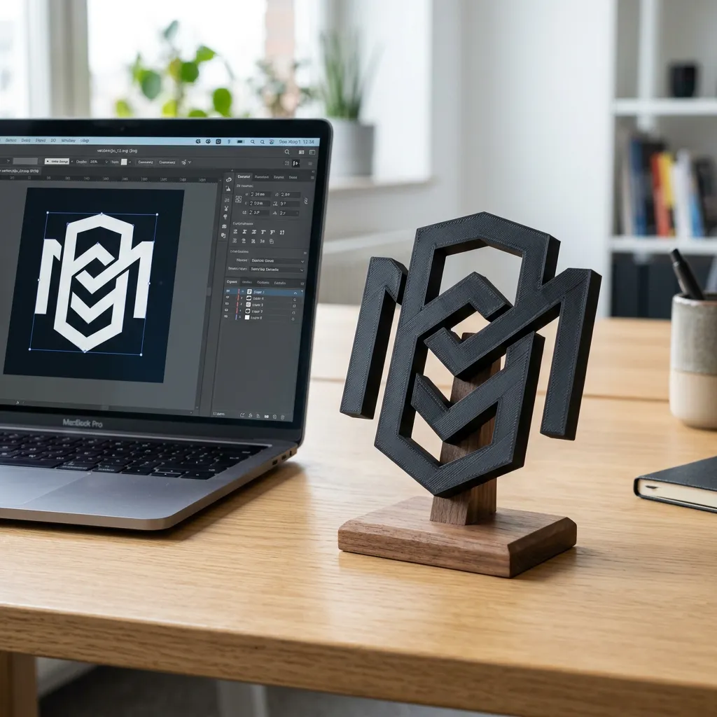
From Bezier Curve to Solid 3D: How SVG Path Extrusion Works
Understanding what happens under the hood helps you create SVGs that convert perfectly. Here is the pipeline:
SVG Parsing: Reading the XML
The parser reads the raw SVG file and extracts all shape elements: <path>, <polygon>, <rect>, <circle>, <ellipse>, and <line>. Each shape is converted into a sequence of 2D points defining its outline. Path commands (M, L, C, Q, A, Z) are interpreted to build the contour geometry. <g> groups and transform attributes are applied to compute the final position of every point in the global coordinate space.
Path Triangulation: From 2D Outline to 3D Faces
Closed shapes are filled by triangulating the interior region. The triangulator handles concave polygons and shapes with holes (created by nested paths with opposite winding directions). The result is a flat 2D mesh of triangles representing the top face of the extrusion. This is the moment when pixel precision is either preserved or lost — our triangulator maintains sub-pixel accuracy because it works directly with the mathematical curve definitions, not a rasterized approximation.
Extrusion: Adding the Third Dimension
The 2D mesh is duplicated and offset by the extrusion depth, creating the bottom face. The edge vertices are connected to form the side walls. The result is a watertight 3D mesh where every face is correctly oriented (normals pointing outward). The extrusion depth is controlled by the height slider — a value of 3mm creates a 3mm thick object. The base plate option adds a flat bottom to the entire model for stability during printing.
Preparing SVGs in Your Design Tool
Each design tool exports SVGs differently. These are the exact settings for each one.
Adobe Illustrator
1. Convert all text to outlines: Select all → Type → Create Outlines (Ctrl+Shift+O). If you skip this, text elements will fail because the system fonts are not embedded. 2. Expand strokes to filled shapes: Select stroked paths → Object → Expand → check "Stroke". Thin strokes produce fragile geometry. 3. Merge overlapping shapes: Window → Pathfinder → Unite. Overlapping shapes create redundant internal edges. 4. Simplify paths: Object → Path → Simplify, set Curve Precision to 95-98%. This reduces control points without visible quality loss and produces smaller STL files. 5. Export: File → Export → Export As → SVG. Settings: Styling = Internal CSS, Font = Convert to Outlines, Decimal = 2, uncheck Responsive.
Inkscape (Free)
1. Convert text to paths: Select text → Path → Object to Path. 2. Stroke to path: Select stroked objects → Path → Stroke to Path. 3. Union overlapping shapes: Select overlapping shapes → Path → Union. 4. Simplify: Path → Simplify (Ctrl+L). Press multiple times for progressively simpler paths. 5. Save as: File → Save As → Optimized SVG. In the dialog: Number of significant digits = 4, uncheck "Enable viewboxing", check "Shorten color values". The "Optimized SVG" export removes Inkscape-specific metadata that adds unnecessary file size.
Figma
Figma does not have native SVG path simplification tools, so prepare your design carefully. 1. Outline text: Right-click text → Outline stroke (this also outlines text in newer Figma versions) or use the "Text to Path" plugin. 2. Flatten: Select your design → right-click → Flatten (Ctrl+E). This merges all layers into a single vector shape. 3. Export: Select the flattened shape → Export panel → SVG. Warning: Figma sometimes adds unnecessary <clipPath> elements. If your SVG does not convert correctly, open it in Inkscape and re-export using the settings above.
Affinity Designer
1. Convert text to curves: Select text → Layer → Convert to Curves. 2. Expand stroke: Select stroked objects → Layer → Expand Stroke. 3. Add/subtract overlapping shapes: Use the Geometry tools (Add, Subtract, Intersect, Xor, Divide) to create clean, non-overlapping shapes. 4. Export: File → Export → SVG. Settings: Rasterize = Nothing, Flatten transforms = checked, Use relative coordinates = unchecked, Add line breaks = unchecked. Affinity exports clean SVGs but sometimes embeds raster previews — make sure "Rasterize" is set to "Nothing" for a pure vector output.
SVG Elements: What Works and What Does Not
| SVG Element | Support | Notes |
|---|---|---|
| <path> | Full support | All path commands (M, L, C, Q, A, Z). Closed paths required for extrusion; open paths may produce thin edges. |
| <rect> | Full support | Converted to path automatically. Rounded corners (rx, ry) are preserved accurately. |
| <circle>, <ellipse> | Full support | Converted to bezier paths. Smooth curves preserved without polygonal approximation. |
| <polygon> | Full support | Straight-line shapes with fill. Self-intersecting polygons may produce unexpected triangulation. |
| <line> | Limited | Lines with stroke only (no fill) produce thin line geometry. Best converted to filled shapes via "Stroke to Path." |
| <text> | Not supported | Text requires system fonts. Always convert text to outlines before exporting your SVG. |
| Gradients | Raster fallback | Gradients trigger automatic rasterization. The shape is filled but precision is lost. Use solid fills for true extrusion. |
| Nested shapes with holes | Full support | Counter-clockwise paths inside clockwise paths create holes. The letter "O" and donut shapes work correctly. |
SVG to STL Questions
- How is this different from uploading an SVG as an image?
- When you upload an SVG as an image to a standard converter, it is rasterized (converted to pixels) at a fixed resolution — typically 512px. A thin line in your SVG becomes 1-2 pixels wide in the raster, which creates a tiny bump in the heightmap instead of a clean extrusion. Our SVG parser reads the actual mathematical path data and extrudes it directly, preserving edges at any resolution. A 1mm line in your SVG becomes a 1mm feature in the STL, regardless of canvas size.
- Why does my SVG produce a flat rectangle instead of my design?
- This means the tool fell back to raster mode. The most common causes: (a) Text was not converted to outlines — use Create Outlines. (b) The SVG contains raster images (PNG/JPG embedded inside the SVG) — remove them or use only vector elements. (c) The SVG uses unsupported features like complex gradients, filters, or clip-paths — simplify to basic paths and solid fills. (d) The file is not a valid SVG — some tools export HTML-wrapped SVGs. Open in a text editor and confirm it starts with
<svg. - Can I control how thick the extrusion is?
- Yes, the height slider controls the extrusion depth. This is a uniform thickness applied to all shapes in the SVG. For different thicknesses on different parts, split your SVG into separate files and convert each with different height settings, then combine them in your slicer. Alternatively, create the depth variation in the 3D model itself using the heightmap mode for the overall shape and SVG extrusion for the raised details.
- What happens to very small details in my SVG?
- Details smaller than your printer's nozzle diameter (typically 0.4mm for FDM) will not print well regardless of the STL quality. Our tool preserves sub-millimeter details in the mesh, but they may be lost during slicing if they are thinner than the extrusion width. For very fine detail work, use a smaller nozzle (0.2mm) or switch to resin/SLA printing which can resolve details down to 0.05mm. Design your SVG with your printer's capabilities in mind.
Advanced SVG Optimization for 3D Printing
Path Count and STL File Size
Every control point in your SVG becomes a vertex in the extruded 3D mesh. A complex logo with 5000 path points produces a larger STL than a simplified version with 500 points. Before exporting: use your editor's path simplification tool (Illustrator: Object → Path → Simplify; Inkscape: Ctrl+L). Aim for ~95% curve precision — this removes ~80% of control points while preserving the visual shape. The difference in the printed model is invisible, but the STL file size can drop from 15MB to 3MB. Faster slicing, faster printing, identical visual result.
Fixing Self-Intersecting and Open Paths
SVGs from some tools contain paths that cross themselves (self-intersect) or are not properly closed (missing the "Z" command at the end). These produce unpredictable extrusion results. Fix: In Illustrator, use Object → Path → Simplify (check "Straight Lines" to convert curves to line segments if self-intersections persist). In Inkscape, Path → Break Apart then Path → Union to reconstruct cleanly. Test: select a path in your editor and check if it has a fill. A properly closed path fills with color. An open path does not fill — these need to be closed before extrusion.
Understanding the SVG ViewBox and Coordinate System
The viewBox attribute (e.g., viewBox="0 0 100 100") defines the SVG's internal coordinate system. Our parser uses this to determine the proportions of the extruded model. Important: the viewBox aspect ratio becomes the aspect ratio of the STL model. A viewBox="0 0 200 100" creates a model that is twice as wide as it is tall. If your exported SVG has a viewBox that does not match your intended 3D proportions, the STL will be distorted. Fix: set the artboard/canvas size in your design tool to the exact proportions you want. Avoid SVGs without a viewBox — they may import at unexpected scales.
Layered SVG Extrusion: Separate STLs for Multi-Color Prints
Design your SVG in separate layers by color. Export each color layer as its own SVG file. Convert each to STL with the same extrusion depth. In your slicer, assign different filaments to each STL. The result: a multi-color 3D print where each color region is a separate physical piece that fits together. This technique requires: all pieces must share a common base height so they align. Use the base plate option on all pieces and set the same base thickness. The pieces will slot together on the print bed like a puzzle.
SVG is for vector art. For photos or raster images, use the appropriate format.